Basic Idea
I wanted to set up a pendulum with a small magnet on its end, place an electromagnet beneath where the pendulum would swing, and then energize the electromagnet briefly from time to time to "nudge" the pendulum so that it would swing "forever". (Note that the electromagnet works best if under the swing of the pendulum, not at the end of the swing, mounted so that it would be hit by the pendulum if it were to swing just a little "too far".)
That's about all there is to it! The project is almost that simple. Why bother to make one? To be sure I could, and the spot I have in mind for this toy is a two story high atrium, and a suitable pendulum gently swinging back and for there will, I think, look rather nice. And be a relaxing sight.
Details....
Definition: Reed switch: Usually two tiny metal leaves in a sealed glass tube, arranged so that when a magnet is near, the leaves come together and electricity will flow through the device. When there is no magnet nearby, the leaves spring apart, and no electricity flows. Usually a single pole, single throw switch.
If, in addition to the electromagnet, you also put reed switches under the arc through which the pendulum swings, then you can use their closures (as the pendulum and its magnet swing over them) to time when the electromagnet is energized. If it isn't turned on and off at the right times, you don't get good results. You might think that one reed switch would do... but using only one gives rise to problems. (You might want to try to figure out what they are before the answer is given farther down the page.)
If your skills are up to it, I suspect that using LEDs and phototransistors to detect the pendulum passing a certain point would give better results. But I used reed switches, and made them work.
I would suggest putting the switches and the electromagnet near the point the pendulum would be over if it were hanging, still, not swinging. This has pros and cons, which I invite you to explore for yourself, if only in your mind. Be sure the reed switch nearest the electromagnet is not so near that turning on the electromagnet will cause the reed switch to close.
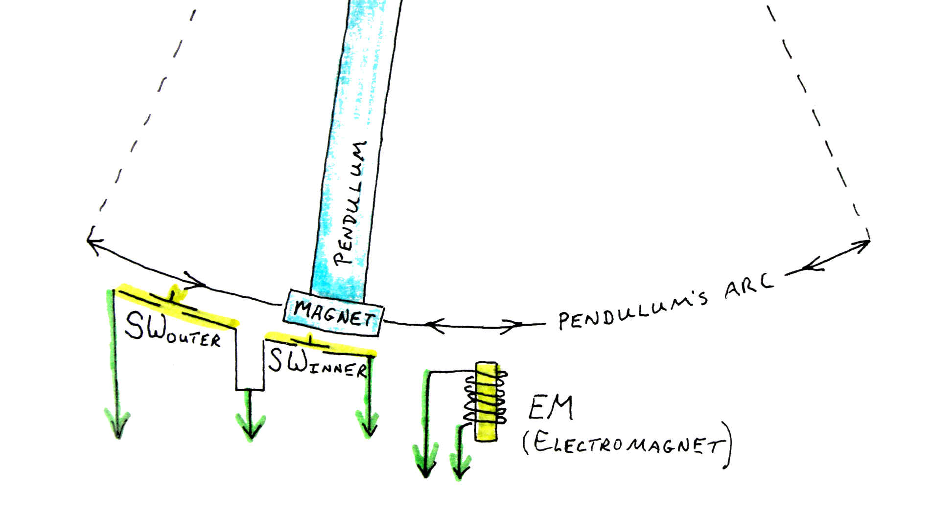
The following diagram should merely recap what you already know. The green arrows (pointing down) represent the five wires which lead away from the pendulum/ switches/ electromagnet to the place where you have the Arduino and other electronic elements. Don't be tempted to combine the two "earth" wires. (More on this later.) "SWouter"and "SWinner" are just shorthand names for the two switches.
Building it... mechanical....
You cannot spend too much time making sure you have a good pendulum. If it isn't well mounted, so that it will swing consistently, you will spend the rest of the time you spend on this project being annoyed. In other words you don't want the setup of switches and electromagnet I had in the prototype!!
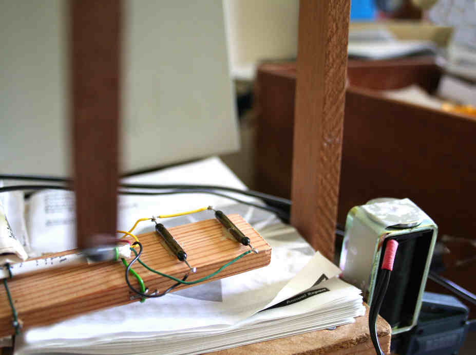
(The blurred vertical at the left is the pendulum, the vertical on the right supports the pendulum.)
The longer your pendulum is the better, within reason.
A heavy weight near the bottom will be helpful. It will help if the center of the weight's gravity coincides with the center of the magnet mounted on the end of the pendulum. (If this is not done, the pendulum will try to twist when the electromagnet pulls on the pendulum magnet.)
I used quite a dinky disk magnet, and mounted it "flat", i.e. with the flat faces horizontal when the pendulum is at rest. Having said that, it is a modern (strong) "dinky" magnet, and I was lucky enough to have a good electromagnet to hand. Neither is a critical element, just use the best of each that you can obtain easily.
The precise positioning of the two reed switches and the electromagnet is critical to the satisfactory working of this toy. You will do yourself a favor if you mount them in a way that facilitates fine adjustments. One of the advantages of the broken- light- beam approach to detecting the pendulum's position accurately, with less effort on the mechanical side, become easier. The spacing between the two reed switches isn't critical... you will probably get away with anything that isn't silly. Put them far enough apart, though, that there will be at least a little time when neither is activated when the pendulum is between them.
Both the Coriolis effect and forces arising from elements in the design can deflect the swing of the pendulum from a nice simple "back and forth" in one plane. So mount your pendulum such that it resists any attempts to deviate.
How you hang the pendulum is up to you; I doubt you need my help, but I've posted a few ideas on the page the link will take you to, if you are interested.
Building it... electrical/ electronic....
The following gives you most of what you need....
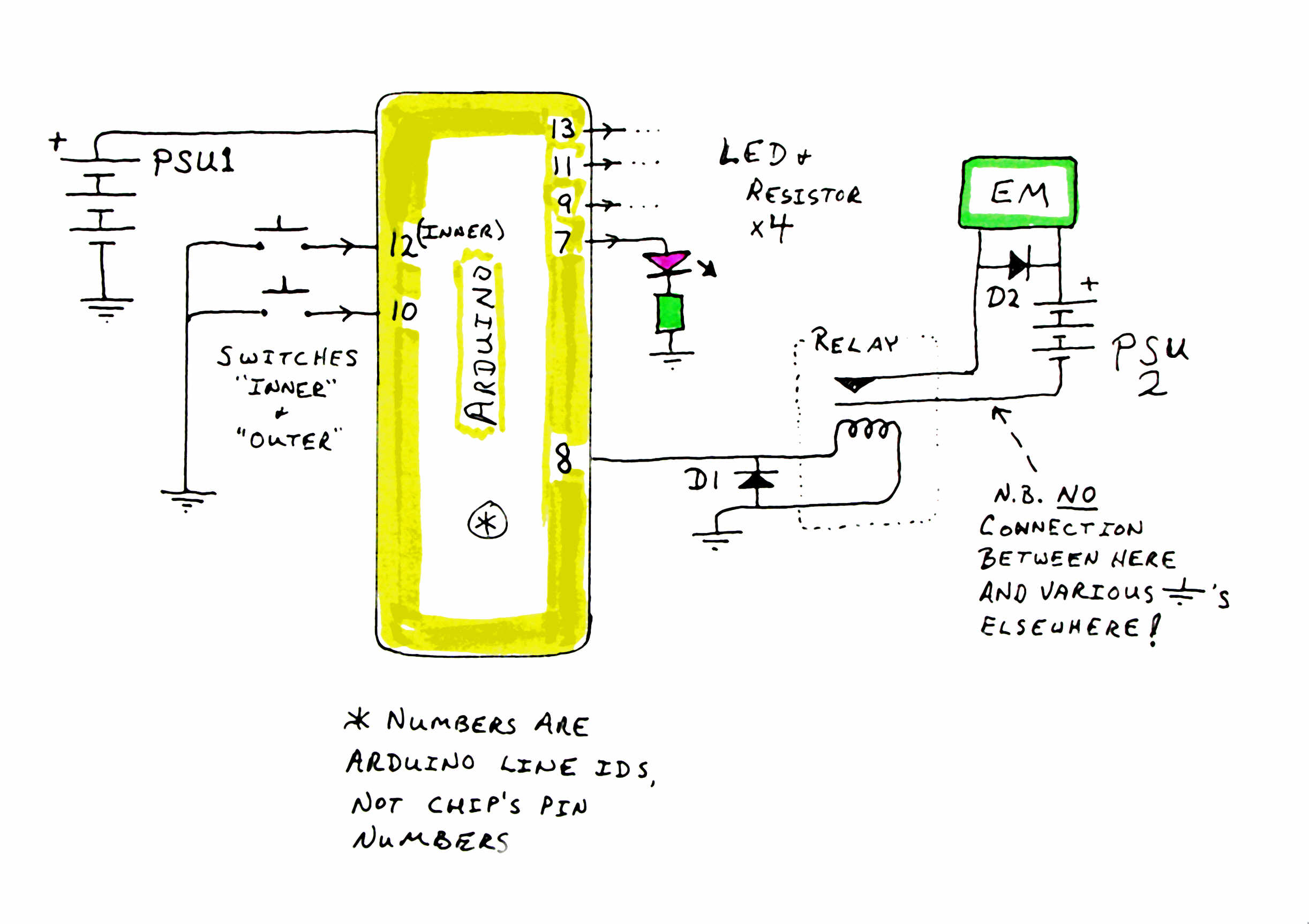
N.B.: I would love to build the whole thing with just one power supply, and it "should" be possible. However, there's something called "field collapse" which you need to know about. Consider the electromagnet in this project. When you connect it to a voltage, electro-magnetism builds up around the electromagnet. When you dis-connect the voltage, that magnetism "collapses" in on the coil, and gives rise to a pulse of high voltage. That much I know and understand. That is why the diode (D2) is present. It is inserted the way it is so that no electricity flows through it when the voltage from PSU2 is applied across the electromagnet. (You'll cause all sorts of problems... unless PS2 is short circuit friendly... if you connect things up with the diode the wrong way 'round.) When the voltage from PSU2 is removed, the role of the diode is to "drain off" the voltage arising from the collapsing field. All of that logic also applies to D1, by the way. Whenever you have a relay in a circuit, you put a diode across the coil thus. 1N4004s work well... just be sure to use something like that, capable of handling significant current. Some of the small "signal" diodes may not be up to the strain.
Continuing the story of why there are two power supplies (PSUs): Years ago, I set out to built a computer controlled model railway. I had a PIC (poor man's Arduino) programmed to control the voltage supplied to the train track. That voltage went into the motor of the train. A motor is, in many ways, just a special electromagnet. And I "blew up" (permanently fried) a number of PICs. I never did figure out why I was destroying my PICs. I looked into a number of things, I took great care, I built protection into everything... and still I destroyed PICs.
You "should" be able to build something like my Perpetual Pendulum without needing two power supplies... but I didn't want to risk damaging my Arduino, hence my cautious, two PSU, design.
One of the LEDs (LEDspare) isn't used at all. You don't need the LEDs for the project to work... but the visual indication of what the Arduino is "seeing" and "doing" can be very useful during troubleshooting, and "costs" nothing. If you decide to dispense with one or more of the LEDs, you can still run the program just as published below.
Electromagnet: I was lucky... I had a nice 12volt solenoid in my junk box. I left its actuator in place, taped to the retracted position. That made a nice iron core to focus the magnetism. I put the current through the coil so that the magnet on the end of the pendulum is attracted to the electromagnet when it is energized. This was to avoid having the pendulum pushed sideways, out of a nice straight arc. If your electromagnet is repelling your magnet, you only have to reverse the connections to the electromagnet. Be sure to do it "downstream" (distal from) the diode... you want to reverse the direction of current flow through the coil, but still present the voltage to the diode as before.
If you have to build your own electromagnet, be careful that the load it places on PSU2 isn't too high. Another component that will be under some strain is the relay. The electromagnet will be energized again and again and again. And when it is energized, there will be what amounts to a brief almost short circuit across the contacts... high current. If your pendulum stops working after a few days or weeks, the relay is the first thing I'd check, assuming that the swing of the pendulum still takes it over the reed relays properly.
There's no reason to site the Arduino right next to the pendulum. The five wires between the electromagnet and the two switches and everything else can be quite long.
So! that's about all I have to say about the system. Here's the software. (There will be a few comments on the software after it....)
/*
Pendulum01
ver 29 May 08

Hardware: 3 LEDs for data output:
LEDInnerRS: Announces state of reed switch nearest center
               of pendulum swing
LEDOuterRS: Announces state of reed switch farthest from
               center of pendulum swing
LEDElectMag: Announces state of output to relay

One output line to control relay to control electromagnet

Two inputs from reed switches.

*/

#define LEDOuterRS 13  //no ; here.
#define LEDInnerRS 11  //no ; here.
#define LEDElectMag 9   //no ; here.
#define LEDSpare 7   //no ; here.

#define SWInner 10 //no ; here.
#define SWOuter 12 //no ; here.

#define ElectMag 8 //no ; here. This output will be used
  // to turn electromagnet on.

//Set up values for the variable LastSwitched
#define inner 0 //no ; here. Not "necessary" but makes code
#define outer 1 //no ; here.        more readable
int LastSwitched = 0;


void setup()
{
pinMode(LEDInnerRS,OUTPUT);
pinMode(LEDOuterRS,OUTPUT);
pinMode(LEDElectMag,OUTPUT);
pinMode(LEDSpare,OUTPUT);

pinMode(ElectMag,OUTPUT);

pinMode(SWInner,INPUT);
pinMode(SWOuter,INPUT);
digitalWrite(SWInner, HIGH);//Turn on internal pull up resistor
digitalWrite(SWOuter, HIGH);
}

void MagnetOnBriefly()
{
/*The LED is not a necessary element, just helpful in
diagnostic work.*/
digitalWrite(ElectMag,HIGH);
digitalWrite(LEDElectMag,HIGH);
delay(290);
digitalWrite(ElectMag,LOW);
digitalWrite(LEDElectMag,LOW);
return;
}

void loop()
{
 if (digitalRead(SWOuter)==HIGH)
           {digitalWrite(LEDOuterRS,LOW);}
            else
           {digitalWrite(LEDOuterRS,HIGH);
            LastSwitched=outer;
            };
 if (digitalRead(SWInner)==HIGH)
           {digitalWrite(LEDInnerRS,LOW);}
            else
           {digitalWrite(LEDInnerRS,HIGH);
            if (LastSwitched==outer){MagnetOnBriefly();};
            delay(40);//debounce
            LastSwitched=inner;
            };
}//End "loop"
==== Discussion of program.... ====
Remember the conundrum set earlier? "Why two switches?"
For the sake of discussion... it didn't happen, really!.... let's imagine that at first I only one switch. Why can't we trigger the electromagnet each time the pendulum goes over it?
You'd be half right. Assuming things are arranged as in the first diagram, and assuming you've wired things so that an energized electromagnet attracts the pendulum, then yes, you want to energize the electromagnet when the pendulum is swinging left- to- right.... which it will be doing half of the time it passes over the switch But! What about the times when the pendulum is swinging away from the electromagnet! You don't want to "call it back" at those times, do you?
By having two switches, you can ask where the pendulum was a moment ago. Do yourself a little table showing the sequence of "switch ons" you get from the two switches as the pendulum swings. Assuming a pretty wide swing, you'll see that the switch that is on goes...
I(nner), O(uter), O, I, I, O, O, I, I....
The right time to turn the electro-magnet on briefly is when the inner switch is on immediately after the outer switch has been on.
Just as a little aside: In this project (and most Arduino work, as far as I'm aware) we are working with the states of the inputs at specific moments. In some electronic control work, we are able to look for and work with "edges", instead of what we're doing here, working with "levels". "Edges" occur when the state of an input changes. A change from low to high is called a rising edge, and the other change is a falling edge. While working with edges is nice in some ways, they are nasty in others. In particular, edges are very brief, so you usually have a way to ask "has an edge occurred since I last asked?" In our Perpetual Pendulum project, we only concern ourselves with levels, and we check and re-check the states of the inputs so often that there will not be a case where one goes high and then low again so quickly that we won't have looked at least once during the brief (in human, but not computer, terms) time it was high.
=== Further discussion... ===
To get you Perpetual Pendulum working well, you'll have to adjust the following to get what is right for whichever you chose to change first....
- Position of electromagnet
- Position of inner switch
- Position of outer switch
- Length of debounce delay*
- Length of time electro-magnet is switched on
Re- the "debounce delay", marked "*" in the list above. It is the one inside the "loop" function. To be honest with you, I'm entirely quite sure why this delay is needed... but it does make a difference to the way the program performs. I suspect it prevents the program from "seeing" the switch close more than once for one pass of the pendulum overhead... although 40ms seems an awfully short time to accomplish this. It works, so I used it!
The length of time the electomagnet is switched on is controlled by the delay in the "MagnetOnBriefly" function. Too long, and when the pendulum is swinging widely, the electro-magnet will limit the swing, as it will pull back on the pendulum after the pendulum has swung past the electro-magnet, and is trying to go out on its swing to the right. If the electromagnet is not on for a long enough period, the magnet on the pendulum will be relatively far away from the electro-magnet for the whole time it is energized. And therefore the attraction between the two will only be minimal.
=== Further discussion.... ===
You may have found the....
#define inner 0 //no ; here. Not "necessary" but makes code
#define outer 1 //no ; here.        more readable
... unexpected. During the program's execution, we need to know which switch was last seen to close. As far as the program is concerned, "0" is a code standing for the inner switch, and "1" is a code standing for the outer switch. We store, say, 0 in the variable "LastSwitched" when the inner switch is seen to close. Once we've done that, we only need to say "if LastSwitched==0...." to set up something to happen if the last switch seen to close was the inner switch.
Because of my defines, we can use the words "inner" and "outer" in place of "0" and "1". The English equivalents for the numerical codes are a little easier for our gray cells to process.
With "inner" and "outer" defined, we can say things like "LastSwitched=inner" and "if (LastSwitched==inner)..."
=== Further discussion.... ====
The heart of the program, shown below, is deceptively simple. If you take out everything except the two lines starting "if", can you rebuild the code to do what has to be done? It would be an excellent challenge for a programming class. I'm not even sure that it is "perfect"... but it does work. I did get some odd behavior for a while (before the delay was added). That odd behavior might also have stemmed from the electro-magnet's magnetism "spilling over" and causing one or both reed switched to close.
Heart of program.....
  if (digitalRead(SWOuter)==HIGH)
           {digitalWrite(LEDOuterRS,LOW);}
            else
           {digitalWrite(LEDOuterRS,HIGH);
            LastSwitched=outer;
            };
 if (digitalRead(SWInner)==HIGH)
           {digitalWrite(LEDInnerRS,LOW);}
            else
           {digitalWrite(LEDInnerRS,HIGH);
            if (LastSwitched==outer){MagnetOnBriefly();};
            delay(40);//debounce
            LastSwitched=inner;
            };
Extensions....
=== Things which might be fun.... Count swings
Add some code so that the number of swings is counted. The easy thing to do would be to put an accumulator in the "MagnetOnBriefly" function... but this is not a good answer! (If you want to pursue one of the other extensions which I'm going to mention in a moment.
It will probably be simplest to count the instances of SWinner being on immediately after SWouter being on.
Once you have started counting the swings, if you want to connect an LCD panel (or other means of output) to the Arduino you can list that, just to amaze people, and/ or try to display a time of day derived from the time-keeping capability of the pendulum. Of course you then have to introduce ways of setting the time of day at the start. All beyond what amuses me... but easy enough to do! (Speaking of "amaze": I have an anemometer (wind speed sensor) which may have turned 10 million times since it's counter was last reset. This figure is a little worrying... the counter's figure sometimes "jumps" due to electrical noise... but the program that monitors it has executed 610,000 passes though its main loop since the last time... not long ago... the program was reset, so who knows?)
=== Things which might be fun.... Auto-restart
From time to time "things" happen. The cat plays with the pendulum, there's a power outage, whatever.
The software given above works while it works, but if things go wrong, the pendulum will stop swinging, and not start again without human intervention. In particular, if for some reason the outer switch doesn't close for a few swings, the electro-magnet doesn't energize for a few swings, and before long the swings are too short for the magnet to reach the outer switch and we are headed towards a dead pendulum.
It would not be beyond the wit of programmer-kind to include some extra code which would "do things" when the outer switch wasn't being closed. The normal system, with its feedback circuit, allows for optimal swinging. But an alternative, "crude", system might be able to get the pendulum swinging well enough for the feedback-driven alternative to start working again.
If such a system were built, then a solar powered (see below), runs-just-when-the-sun-is-out version of the Perpetual Pendulum becomes do-able.
=== Things which might be fun.... Alternate power
Depending on the match (or lack thereof) between your electro-magnet and it's PSU, the strain of supplying adequate voltage to the electro-magnet may be over-stressing the PSU.
You could solve this, and perhaps also get better overall performance, by using PSU2, through a resistor, to charge a capacitor. The electro-magnet would then be powered by the charge in the capacitor when the relay closed.
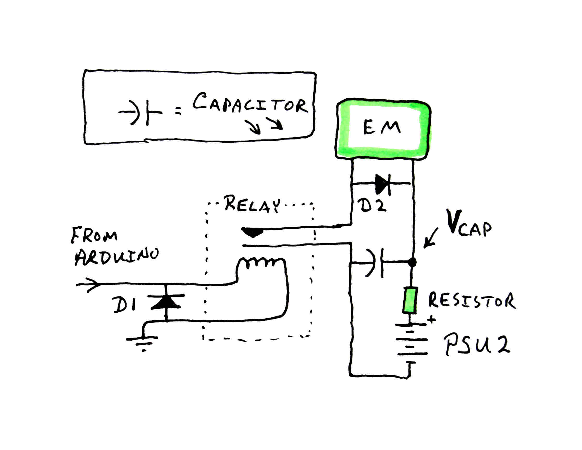
Such a circuit will "save up" electricity in the capacitor, and "deliver" it in a burst when the contacts of the relay close.
If you had enough photovoltaic solar cells to generate a suitable voltage, it wouldn't matter if the current supplied was weak. Of course, the system would need a night light or other to see it through the night.
With the capacitor circuit, a new problem arises. How often do you close the contacts on the relay? The fun of design work is in imagining and exploring the alternatives, weighing up their pros and cons.
The "close how often" question has many possible answers.
If your power supply, though weak, is at least constant (i.e. not solar power!), you could program the system to zap the electro-magnet once every, say, five swings. Or more or less, depending on your PSU.
If you want to get fancier, you could monitor the voltage marked V-CAP on the diagram. As the capacitor charges up, that voltage will rise. Now... if you have overcome the problems discussed previously about keeping the voltages in the Arduino strictly separate from the power for the electro-magnet, you could monitor V-CAP with one of the Arduino's analog inputs.
You could also, with a transistor or so, put an extra "switch" in series with the contacts of the relay. The Arduino would "ask" for an electro-magnet pulse on every swing of the pendulum, but the transistor(s) would prevent that from happening until there was adequate charge in the capacitor. Again, this would tap into V-CAP to know when the capacitor ware adequately charged.
If the solar power idea is attractive, you can combine a few things for a "full" answer....
I'd still go with two power supplies... one for the Arduino, one for the electro-magnet. Each would involve, in essence, the circuitry found in emergency lights. During the day, solar cells would be used to charge batteries. Voltage regulators would allow power to pass to the Arduino and electro-magnet as needed, and "extra" electricity would be passed for storage to the batteries to see the system through the night.
No comments:
Post a Comment